
Most push buttons have momentary action. Locking types (ON / OFFor even to“maintained” actuation) are often larger, with a deeper body, a bit more expensive, and they often aren't available in the style you want to use. So you may be stuck in your development if you need a small on/off switch to lock power to a load. The circuit in the figure below shows how you can use a simple momentary acting SPNO (single pole, normally open) push button switch to latch power to a load.
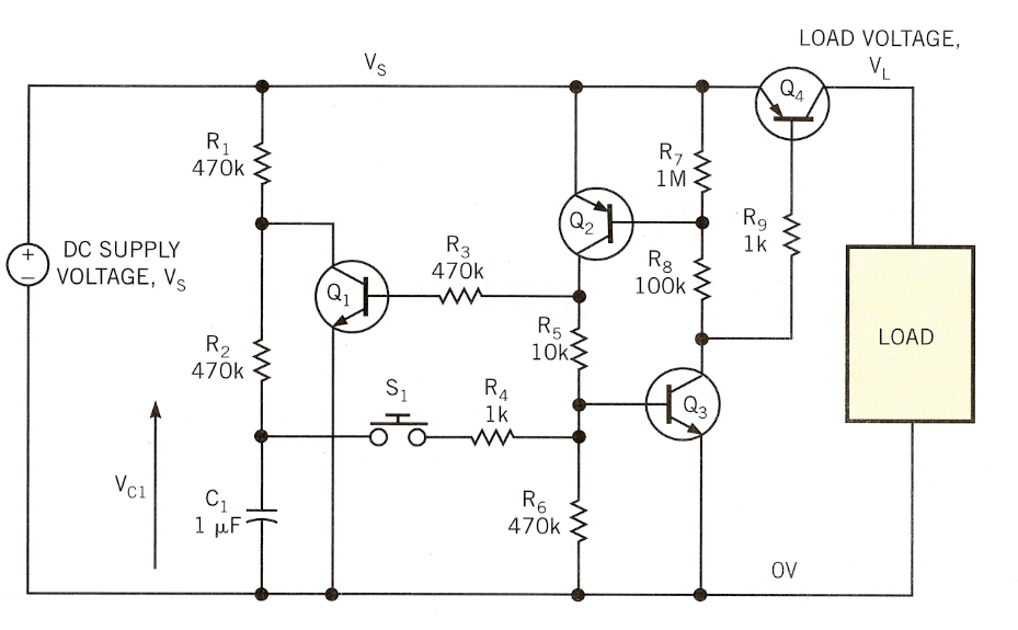
Requiring only a handful of common components, the circuit operates over a wide voltage range and is ideal for single-cell applications because it can operate at voltages as low as 1 V or less. Transistors Q 2 and Q 3 form an SCR type structure which functions as a simple latch, Q 4 powers the load and S 1 is the momentary push button switch.
When you first apply the supply voltage, Vs, all four transistors are turned off and capacitor C1 charges through R1 and R2, until its voltage, VC1 equals Vs.
The circuit is now in its off or unlocked state and the charging voltage, VL, is 0V. A momentary closure of the push button, however, causes C1 to dump its charge into the base of Q3, which conducts and provides bias for Q2 and Q4, both of which activate. Q2 now provides base bias for Q3 via R5, and also for Q1, via R3.
The circuit is now in its enabled or latched state and remains so even if S1 is open. The load is now energized, and VL, is approximately equal to Vs. Transistor Q1, is now saturated, causing C1 to discharge via R2, so that VC1 drops to a few tens of millivolts (collector-emitter saturation voltage of Q1). Another momentary closure of the push button couples this low voltage to the base of Q3, turning it off. As a result, all four transistors turn off and the circuit returns to its off or unlocked state. The load is now de-energized and VL drops to 0V.
Because Q1 is now off, C1 begins charging again through R1, and R2 so that another momentary closure of S1 latches the circuit again. The time delay capacitor C1 acting with R1 and R2 provides debounce for the push button, so that contact bounce has no effect on the desired latching function. Without the RC timer, the circuit would cycle on and off every time you press the push button and end up in an indeterminate state. Although Figure 1 shows a value of 1μF, other values may be more appropriate for a particular application, so experiment! None of the resistor values are particularly critical, and the values shown in Figure 1 are fairly optimal for a supply voltage of around 1 to 1.5 V – in other words, a single cell.
À des tensions plus élevées, les valeurs de résistance devraient augmenter proportionnellement, bien que vous deviez maintenir R2 et R4 constants à environ 470 et 1 kΩ , respectivement. Le maintien de la constante de temps R2 -C1 , fixée à quelques centaines de millisecondes assure que le temps de décharge du condensateur n’est pas excessif ; sinon, une fois que le circuit a été verrouillé, il peut s’ensuivre un délai trop long avant qu’il puisse être déverrouillé. La résistance R4 limite le courant circulant de C1 dans la base de Q3 à un niveau sûr; sa valeur doit être assez faible pour s’assurer que R5 et R6 ne déforment pas la tension apparaissant à la base de Q3 lors de la fermeture de l’interrupteur. Vous devez dimensionner la résistance R1 en fonction de la tension d’alimentation que vous utilisez. Pour une valeur donnée de R2 , R1 , détermine le temps que met VC1 pour remonter vers Vs , immédiatement après le déverrouillage du circuit. En d’autres termes, la valeur de R1 détermine le temps nécessaire pour « amorcer » le circuit afin qu’il soit prêt à être à nouveau verrouillé. Si R1 est trop grand, il devient impossible de verrouiller le circuit peu de temps après qu’il a été déverrouillé. En revanche, si R1 est trop petit, il peut imposer une consommation de courant trop importante sur Vs lorsque le circuit est verrouillé.
Additionally, for a particular value of Vs, R1 must be large enough that VC1 does not rise too quickly after the circuit is unlocked, or it might close the latch again before the switch opens.
You may need some experimentation to determine the optimal value of R1, but with C1 =1μF and R2 =470 kΩ, the test circuit worked well with a value of around 470 to 680 kΩ at Vs =1V and of approximately 4.7 MΩ at Vs =10V.
Transistors Q1 to Q3 can be any type of small signal with good current gain (moderate to high forward current gain). Power switch Q4 should have a low VCE (SAT) to ensure that most of the supply voltage is supplied to the load when the circuit is locked. You should select resistance R9 to provide enough base training for Q4; the value depends mainly on Vs, the load current and the saturated current gain of Q4. The circuit provides an inexpensive way to derive a latching function from a momentary pushbutton and, like a mechanical latching switch, the quiescent (unlatched) current consumption is zero.